Background:
This is a fun engineering design project that I worked on in my spare time to fine tune my SolidWorks skills and centrifugal compressor design knowledge. At my most recent job, I had the unique chance of being part of the design team that worked on creating integrally geared compressors. I had the privilege to contribute to the design of the volutes, rotor assembly, bull gear assembly, tilting pad journal bearings, and gearbox.
Design:
This is a two stage integrally geared centrifugal compressor (known as IGCs), which is made up of one rotor assembly and a bullgear shaft assembly. The bullgear shaft is driven by an electric motor's shaft (not pictured), which are joined together by a coupling. Note that the speed of the shafts in my animation are slowed down for visual purposes. In reality, the shafts rotate at thousands of rpm.

Operation:
Integrally geared compressors can be used in many industries due to their flexibility, and are used extensively in the petrochemical industry. They can be designed for low flow/high pressure or high flow/low pressure applications. The multi-shaft configuration gives the additional benefit of allowing for inter-cooling between stages, and thus allowing for higher compression efficiency when compared with in-line configuration compressors.
Many gases can also be used by these compressors by tweaking the design of construction materials and sealing systems. Common gases include: air, chlorine, nitrogen, and natural gas. Flows can vary from 500 to 50,000 m3/h (300 to 30,000 cfm), with discharge pressure up to 100 bar (1,500 psi).
The general operation of an IGC using air as the gas with two stages and using water cooling, is as follows: air enters in an axial direction at the impeller eye through the inlet (after being filtered), air is compressed by the first stage impeller and diffuser, part of the pressure rise occurs when air has its flow changed to radial and is accelerated by the impeller vanes and centrifugal forces, the rest of the pressure rise occurs when the flow is then decelerated in the diffuser, it then exits the volute at nearly the same velocity as it entered (but at a higher pressure), air has heat removed in the first stage inter-cooler, air is then compressed further in the second stage, air exits the volute to the after-cooler, and then leaves to the desired system.
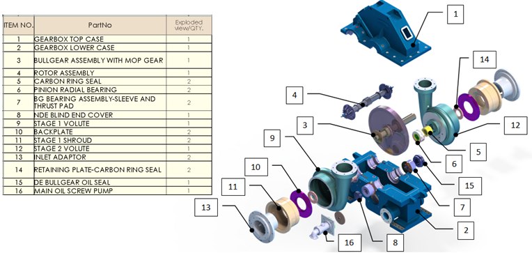
Bill of Materials:
This project is on-going and I will continue to add more as time allows. Soon, I plan to add the inlet guide vane (IGV) and actuator, add the fasteners, fix the split line O-ring routing, add the motor, add thrust collars, add covers, add the inter-stage piping and coolers, and update the shaft seal models.
No comments:
Post a Comment